CET Fire Pumps
CET Attack Pac Skid Unit
CET Attack Pac Skid Unit
Gas Engines:
| 20HP Kohler Mid-Range 20hpKHL-MR Flows: MAX FLOW: 290 GPM MAX PRESSURE: 220 PSI 265 GPM @ 50 PSI 140 GPM @ 150 PSI 60 GPM @ 200 PSI |
20HP Honda High Volume 20hpHND-1D MAX FLOW: 570 GPM MAX PRESSURE: 110 PSI 470 GPM @ 25 PSI 285 GPM @ 75 PSI 130 GPM @ 100 PSI |
20HP Honda Mid Range 20hpHND-MR Flows: MAX FLOW: 300 GPM MAX PRESSURE: 205 PSI 240 GPM @ 50 PSI 125 GPM @ 150 PSI 60 GPM @ 200 PSI |
Gas Engines:
| 20HP Kohler High Volume 20hpKHL-1D Flows: 485 GPM @ 10 PSI 430 GPM @ 25 PSI 350 GPM @ 50 PSI 140 GPM @ 100 PSI 65 GPM @ 125 PSI |
20HP Honda High Pressure 20hpHND-HP Flows: 140 GPM @ 50 PSI 100 GPM @ 150 PSI 40 GPM @ 25 PSI 25 GPM @ 275 PSI |
20HP Kohler High Pressure 20hpKHL-HP Flows: 160 GPM @ 50 PSI 125 GPM @ 100 PSI 90 GPM @ 150 PSI 60 GPM @ 200 PSI 30 GPM @ 250 PSI |
Gas Engines:
| 23HP Vanguard Pressure & Volume 23hpVGD-MR Flows: MAX FLOW: 300 GPM MAX PRESSURE: 225 PSI 265 GPM @ 50 PSI 150 GPM @ 150 PSI 80 GPM @ 200 PSI |
18HP Vanguard High Pressure 18hpVGD-HP Flows: 115 GPM @ 50 PSI 100 GPM @ 100 PSI 70 GPM @ 150 PSI 45 GPM @ 200 PSI 20 GPM @ 250 PSI |
38HP Kohler Pressure & Volume 38hp-KHL Flows: MAX FLOW: 675 GPM MAX PRESSURE: 190 PSI 465 GPM @ 25 PSI 380 GPM @ 50 PSI 225 GPM @ 100 PSI |
Diesel Engines:
| 21HP Kubota Mid-Range Diesel 21hpDSL-MR MAX FLOW: 250 GPM MAX PRESSURE: 190 PSI 230 GPM @ 50 PSI 165 GPM @ 100 PSI 110 GPM @ 150 PSI |
25HP Kubota Mid-Range Diesel 25hp-DSL-MR Flows: 315 GPM @ 10 PSI 300 GPM @ 50 PSI 230 GPM @ 100 PSI 145 GPM @ 150 PSI |
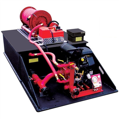
The CET Attack Pac Skid Unit comes with a tank, live hose reel and/or crosslay and portable fire pump.
The CET Drop In Units can be combined into a single one-piece assembly that can be slipped onto a truck bed, trailer, or into a body and used for flowing water and or foam on a structural fire, car fire or wildfire.
The most common wildland and urban interface fire engines in North America combine a small truck with a water tank and a high performance portable pump. Municipal/industrial fire departments and all forestry fire authorities use drop-in units.
Attack Pac (standard unit with 200 gallon tank):
Dry Weight: 740 lbs
Wet Weight: 2,500 lbs
Specifications:
- 200 fully baffled propopylene water tank
- 20hp mid range fire pump
- 265gpm at 50psi, 190gpm at 100psi, 115gpm at 150psi and 45gpm at 200psi
- 3 gallon fuel tank
- Lighted control panel
- Low profile electric rewind hose reel
- 1 inch x 100 foot booster hose
- 2.5 inch tank to pump 1/4 turn ball valve
- Steel manifold with multiple outlets
- 1.5 inch service line with cap and chain
- 3/4 inch pressurized garden hose connection
Options:
- Increase water tank and hose reel sizes
- Diesel engine available
- Pre-connect hose tray with connection
- Set of chrome outriggers with 3 ways rollers
- Scotty around the pump foam system with integrated foam cell
- Storage frame
- Stainless steel piping
- Quiet Muffler
Foam Cell (optional):
5 gallon foam cell (150 gallon tank)
8 gallon foam cell (200-225 gallon tank)
10 gallon foam cell (250-500 gallon tank)
Water Tank:
The water tank shall be constructed of 1/2" thick polypropylene sheet stock with PolymarCo-PP resin. Water tank shall be welded with Heavy Duty extruded joint. The material shall be of a certified, high quality, non-corrosive, stress relieved thermo plastic, black in color with a textured finish, and UV stabilized for maximum protection. The skid type water tank shall be of a standard configuration and shall be so designed to have complete modular slide in capability. The unit shall incorporate transverse partitions manufactured for 3/8" PT2E polypropylene which shall interlock with a series of longitudinal partitions constructed of 3/8" PT2E polypropylene. All swash partitions shall be so designed to allow for maximum water and air flow between compartments and are fully welded to each other as well as to the inside of the tank. The passenger side rear wall of the tank shall have a standard built in sight gauge 3" in width, and 70% transparent.
Fill Tower & Tank Cover:
The tank shall be equipped with a combination vent/overflow and manual fill tower. The fill tower shall have a 8" x 8" x 8" square hinged type cover. The tower shall be located in the right rear corner of the tank. There shall be a vent / overflow installed inside and to the extreme rear of the tower approximately 2" down from the top. This vent / overflow shall be of a standard schedule 40 polypropylene pipe with minimum ID of 3". The vent / overflow shall be piped internally toward the front and exit out the front tank wall with a 1/2" extension past the front tank wall. The tank cover shall be constructed of 1/2" thick PT2E polypropylene, black in color, UV stabilized.
Tank Capacity:
The tank shall have a capacity of 200 U.S. gallons of water.
Sump:
The floor of the tank shall be manufactured from 3/4" PT2E polypropylene. There shall be one (1) sump as standard per tank. The sump shall be integral to the tank floor and be a minimum of 3/8" deep recessed into the floor. The sump shall not be visible from or protrude through the bottom of the tank.
Tank Outlets:
There shall be two standard tank outlets located in the same vertical plane on the driver side rear wall of the tank. One (1) 2-1/2" female NPT tank to pump suction fitting and one (1) 1-1/2" female NPT tank fill fitting with flow deflector
1" Tank Drain:
There shall be a 1" tank drain to the rear side of the tank with a brass plug.
Tank Mounting Blocks:
The cover shall incorporate two (2) booster reel mounting blocks that shall accommodate two (2) each sliding nut fasteners. These 4" large mounting blocks shall be welded to the covers running from the rear edge of the tank forward to the front edge.
Skid Base:
There shall be a full width skid base manufactured of 3/4" PT2E polypropylene welded to the tank. This base shall be 48" wide by 96" long and shall extend 34" past the tank in the rear to allow for pump mounting. The pump mounting area shall be supported by 1/2" PT2E polypropylene gussets approximately 15" high by 32" long. The gussets shall be equipped with 2" holes to assist in lifting the unit. The mounts shall allow for the truck to be secured directly to a truck bed without the need for any skid frame work underneath.
Tank will be baffled in accordance with latest NFPA requirements.
Pump:
The pump shall be a CET DI-PFP-20hpKHL-MR single stage centrifugal pump, bolted directly to the engine, with a 2.5" NPT suction inlet, and a 1.5" NPT discharge outlet. The volute and pump head shall be a lightweight, high strength, seawater resistant, aluminum alloy. The impeller shall be a bronze enclosed type for maximum efficiency, fully machined and balanced. The engine crankshaft shall serve as the pump shaft, with the impeller mounted directly on the crankshaft. The shaft seal shall be self-adjusting, self lubricating, mechanical type.
The pump piping shall be flexible to prevent any breakage caused by vibration.
The pump shall be capable of a maximum discharge volume of 265 GPM. at 50 PSI, and a maximum discharge pressure of 200 PSI while pumping 45 GPM. In the center of the performance curve, the pump shall be capable of pumping 115 GPM at 150 PSI and 190 GPM at 100 PSI.
Pump Engine:
The pump shall be driven by a 4-stroke Kohler gasoline powered, 20 horsepower "V" Twin engine. The engine shall be air cooled, 12 volt electric start with recoil backup. The engine shall be fueled from a 3 gallon separate fuel tank which is to be mounted to the skid cover. The engine shall be connected with a quick disconnect weather proof style connection.
Pump Controls:
A control panel shall be supplied and installed on the pump. The controls shall consist of a master switch, key start and a 2.5" diameter discharge pressure gauge.
Exhaust Priming System:
The pump engine shall be equipped with an exhaust venturi type primer capable of 15' - 20' lift for fast positive priming.
Suction Piping:
All piping on the suction side shall be made of steel (welded joints) schedule 40. The suction piping, the pump and the discharge shall be tested to 400 PSI.
The suction piping shall consist of a 2.5" tank to pump line with a 2.5" flexible rubber hump hose to minimize flex and vibration between the pump and the tank.
Between the tank and the pump there shall be a 2.5" industrial valve. This valve shall remain open to pump from the tank. This pipe shall have a tee into the suction side of the pump, and shall continue to the rear of the truck for overboard suction.
The overboard suction connection shall have a 2.5" NST male adapter and a 2.5" NSTF cap with retaining cable
Work Line Side of Manifold:
On the driver side of the manifold there will be as standard two (2) 1" NPT and two (2) 1 1/2" NPT discharge outlets.
Other Valves:
Other openings will be utilized accordingly when pre-connects, booster reels and other accessories that require pressurized water are specified.
Discharge Valves:
All valves larger than 1" shall be a fire service type drop out style ball valve which shall have a hard-coated anodized, high-strength, light-weight aluminum alloy body with rugged stainless steel ball and two PTFE seats.
The valves shall be capable of bi-directional flow with a minimum working pressure rating of 250 psig.
All stainless steel parts shall be made from 300 series material. The valves shall NOT require lubrication of the seats or any other internal waterway component and shall be capable of swinging out of the attached waterway plumbing for easy maintenance, with the removal of six (6) to eight (8) bolts.
Any required valve 1" or smaller, unless otherwise specified, shall be a standard plumbing style industrial ball valve
Discharges Manifold:
There shall be a discharge manifold plumbed directly to the discharge side of the pump to incorporate discharges at the rear of the unit.
This discharge manifold shall be 2" x 2" square minimum and be welded on all sides to prevent leakage. The manifold will be made from industrial galvanized steel and painted red in color.
Discharges to Rear of Unit:
(One) 1-1/2" fire grade valve drop out style with handle and 1 1/2" NSTM threads shall be furnished with a cap and chain.
(One) 3/4" garden hose thread discharge will be mounted on the discharge manifold facing the rear of the unit utilizing a industrial ball valve and will be equipped with a cap and chain.
Tank Fill:
There shall be one (1) 1" Industrial Ball valve plumbed via high pressure hose from the manifold to the Tank Fill inlet noted on the tank for the purpose of filling the tank and re-circulating water during stagnant pump operations.
12V Electric Rewind Low-Profile Booster Reel:
A Low Profile Hannay 12v electric rewind booster reel capable of handling a maximum of 100' of 1" rubber only booster hose shall be supplied and installed on the tank top. The hose reel shall be protected against power shortage.
The reel shall have a push button rewind control and a backup geared crank rewind handle.
The reel shall be equipped with a 1" NPT 90 degree swivel inlet, and a 1" NST outlet riser.
The reels discs and drum shall be manufactured of steel and be red in color.
1" NST Rubber Booster Hose:
The booster reel shall be equipped with 100' of 1" NST standard rubber booster hose.
Returns Policy
You may return most new, unopened items within 30 days of delivery for a full refund. We'll also pay the return shipping costs if the return is a result of our error (you received an incorrect or defective item, etc.).
You should expect to receive your refund within four weeks of giving your package to the return shipper, however, in many cases you will receive a refund more quickly. This time period includes the transit time for us to receive your return from the shipper (5 to 10 business days), the time it takes us to process your return once we receive it (3 to 5 business days), and the time it takes your bank to process our refund request (5 to 10 business days).
If you need to return an item, simply login to your account, view the order using the "Complete Orders" link under the My Account menu and click the Return Item(s) button. We'll notify you via e-mail of your refund once we've received and processed the returned item.
Shipping
We can ship to virtually any address in the world. Note that there are restrictions on some products, and some products cannot be shipped to international destinations.
When you place an order, we will estimate shipping and delivery dates for you based on the availability of your items and the shipping options you choose. Depending on the shipping provider you choose, shipping date estimates may appear on the shipping quotes page.
Please also note that the shipping rates for many items we sell are weight-based. The weight of any such item can be found on its detail page. To reflect the policies of the shipping companies we use, all weights will be rounded up to the next full pound.
Related Products

CET Fire Pumps
CET Econo Pac Skid Unit
CET Econo Pac Skid UnitThe CET Econo Pac Skid Unit comes with a tank, a live hose reel and 6HP Honda CET portable fire pump. This is combined into a single one-piece assembly that can be slipped onto...

CET Fire Pumps
CET Forest Pac Skid Unit
CET Forest Pac Skid Unit The CET Forest Pac Skid Unit comes with a tank, live hose reel and a 6HP Honda CET portable fire pump.This unit can be combined into a single one-piece assembly that can be...

CET Fire Pumps
CET Ready Pac Drop In Skid Unit
CET Ready Pac Drop In Skid UnitThe CET Ready Pac Drop In Skid Unit comes with a 6 HP Honda CET Twin Impeller Pump and 200 gallon water tank.A tank, a portable fire pump with an engine: these can be...


CET Fire Pumps
CET Skeeter UTV Skid Unit
CET Skeeter Space Pac Skid Unit The CET Skeeter Space Pac Skid Unit comes with a tank, patient transport and fire pump that can be combined into a single one-piece assembly slipped onto a small...


CET Fire Pumps
CET Drop In Water Skid Tank, 200 Gallon
CET Drop In Water Skid Tank, 200 Gallon, 48" x 96"The CET Android Drop-In Skid Tank is built with quality and warrantied for life.Features:48" x 96"Separate and distinct foam cellsCuts down divided...


CET Fire Pumps
CET Drop In Water Skid Tank, 500 Gallon
CET Drop In Water Skid Tank, 500 Gallon, 48" x 96"The CET Android Drop-In Skid Tank is built with quality and warrantied for life.Features:48" x 96"Separate and distinct foam cellsCuts down divided...